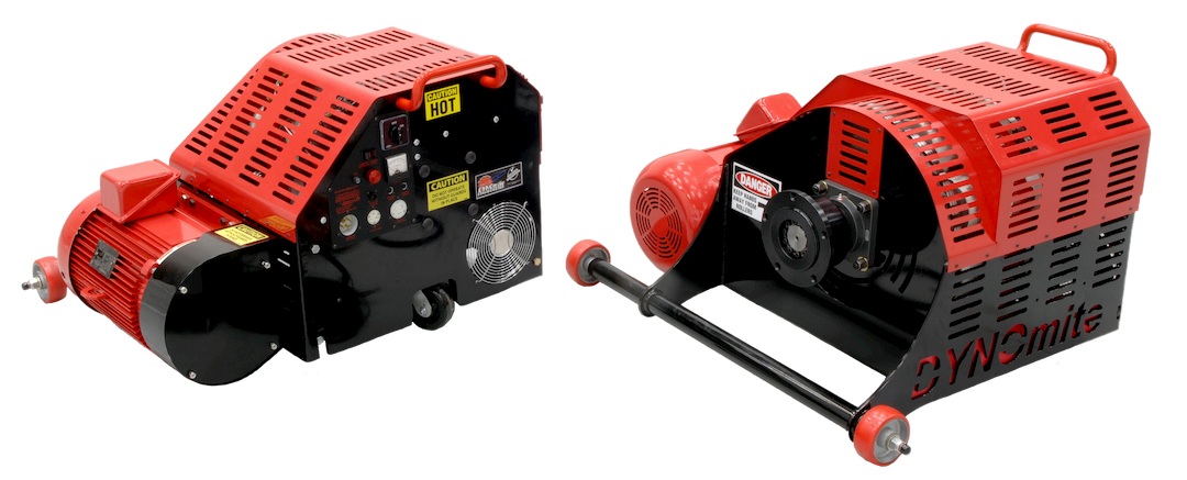
Overview
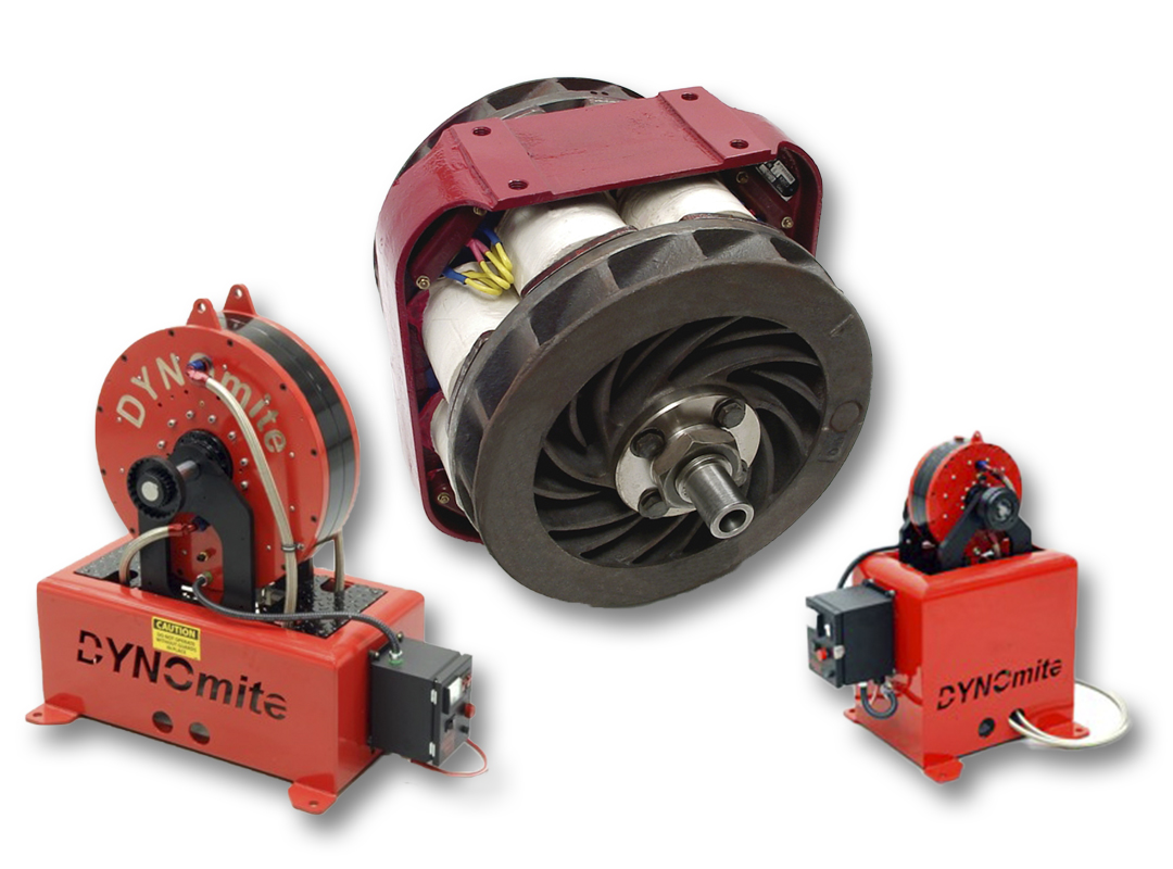
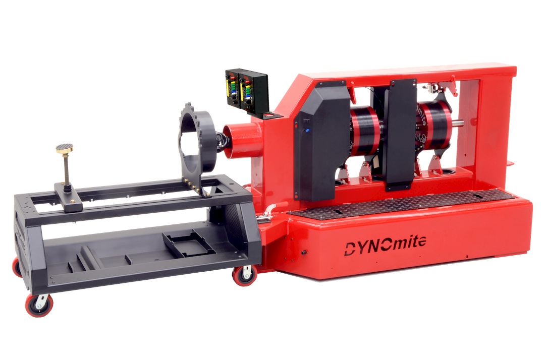
Includes: 9″ toroid Siamese Trunnion style water brake absorber, S-Beam Load Cell, DYNOmite-Pro data-acquisition computer, manual load valve, 28-channel data harness, stainless braided hoses with aircraft fittings, and manual.
Trunnion Engine Dynamometers variations:
- 400+ HP
- 800+ HP
- 2000+ HP
Specs
DYNOMITE DATA-ACQUISITION COMPUTER | |
Hardware configuration |
Expandable, hybrid (surface-mount and thru-hole) multi-layer board system |
Voltage requirements (DAQ only) |
Runs on 120-volt 60-Hz AC, 240-volt 50-Hz AC, or 12-volt DC (specify) |
Approvals |
CE and/or UL approved (per locale) |
Board type and channel capacity |
Pro, PC linked − 28 channel |
Expansion capacity upgrades |
28-channel capable subsystem − standard (112+ channel optional) |
Data rate |
User-selectable rates up to 200 (1,000 optional) recordings per second (per channel) |
Transducer wiring interface |
Quick-disconnect data harness − 28-channel (included) |
Calibration |
Non-volatile setup memory |
Atmospheric correction |
Standard, SAE, DIN, JIS, ECE, J1995, Custom |
Wireless-Integration Options |
Available |
Recording features |
Smart Record™ automated recorder triggering |
Data interface |
User selectable, USB or RS-232 serial port, output to a PC − via DYNO-MAX software option |
Third-party data-output interface options |
Free Windows driver for National Instrument’s Lab View™ available |
Temperature sensor |
0 to 255 Fahrenheit [-18 to 124 Celsius] thermistor (included) |
Standard and optional sensor inputs |
RPM, torque, frequency, flows, pressures, thermocouples, thermistors, 0-5 volts, Lambda, smoke opacity, position, etc. |
Standard and optional control outputs |
Ignition shut-off, relay control, load-control stepper output, 0-5 volt D/A, etc. |
TORQUE TRANSDUCER | |
Configuration |
Environmentally sealed, moment-length independent, torque arm |
Maximum displayed torque |
Unlimited ft-lbs [N-m] − real-time and playback |
Load-cell range |
0 to 2,000 foot pounds [0 to 678 Nm] – Varies based on specific model |
Load-cell signal-output gain |
3 millivolts/volt |
Load-cell resolution | Better than 0.02% of full-scale accuracy − typical |
Strain gauges | Linearized full-bridge strain gauges in balanced Wheatstone bridge |
Advanced linearization (software) | User-configurable edit table (interpolated deviation map) |
System torque resolution | Better than 0.1% of full-scale accuracy − typical |
Calibration features | Semi-automatic calibration of zero offset |
Drift stabilization | Ratiometric supply-voltage and temperature compensation |
ABSORBER MOUNTING FRAME (OPTIONAL) | |
Configuration |
Heavy-duty steel absorber-mounting base |
Mechanical cart construction | Heavy-duty formed-steel frame − with mounting holes and hardware for absorber’s trunnion mounts, integral feet for floor anchoring |
Absorber to engine coupling | Inline 1:1 ratio (via customer-supplied driveshaft) to absorber’s 1410-style flange − included |
Driveshaft | 1410 style – telescoping drive shaft (custom dampening-specifications – optional) |
Driveshaft guard | Installer responsibility |
Installation | Bolts to floor, with appropriate (customer supplied) anchoring hardware |
ENGINE-CART (OPTION) WEIGHT CAPACITIES | |
Maximum dynamic load | 2,000 pounds [908 kg] (other cart options available) |
Maximum static load | 2,000 pounds [908 kg] (other cart options available) |
POWER CAPACITY (RPM DEPENDENT)* | |
Notice | *Actual load capacity depends on test RPM (typical loading plots available) − liquid-cooled absorbers require a minimum water flow of 1 gpm @ 30 to 60 psi for every 20 continuous Hp. |
Maximum displayed power | Unlimited Hp [KW] − real-time |
Maximum displayed torque | Unlimited Ft-Lbs [N-m] − real-time |
Maximum continuous power | Up to 800+ Hp [597+ KW] @ 7,000 RPM − 200+ Hp [149+ KW] @ 2,500 RPM (see absorber’s load chart − other ranges available) |
Maximum continuous torque | 920+ Ft-Lbs [1,247+ Nm] @ 3,500 RPM (see absorber’s load chart – other ranges available) |
Maximum RPM | 10,000+ RPM (other ranges available, see absorber load charts) |
ENGINE (AND ABSORBER) TACHOMETERS | |
Range | 0 – 32,000+ RPM real-time display (user reconfigurable) |
Timing reference | Quartz-crystal calibrated |
Resolution | 0.1 RPM (typical) |
Primary RPM signal | Absorber-mounted hall-effect sensor |
Signal compatibility | User adjustable trigger voltages − pulse type selectable from ½ to 240 PPR |
Alternate tachometer options | Optional ignition and optical RPM pickups |
ABSORBER AND LOAD CONTROL | |
Absorber to Engine coupling | Inline 1:1 ratio (via customer-supplied driveshaft) to absorber’s 1410-style flange − included |
Absorber speed / RPM regulation | Manual “Standard-Flow” load-valve control − included (optional electronic auto-load control, closed-loop PID, with automated test cycles via DYNO-MAX) |
Absorption method | Siamese-rotor 13″ toroidal-flow water-brake absorbers with manual “Standard-Flow” load-valve control − included (electronic auto-load control optional) |
Absorber sensitivity | User-adjustable outlet orifices (included) |
Bidirectional capable | Yes |
Hoses | Stainless-steel braided with anodized aircraft fittings − for inlet control, outlet drains, and venting (included) |
Power requirements (for optional load control) | 10-amps @ 12-volts DC |
Rotor | Toroidal-flow, low-inertia billet-aluminum alloy − standard (heavy-duty stainless steel optional) |
Throttle (torque / power) regulation (optional) | Electronic-throttle control of torque, power, or % − including automated test cycles via DYNO-MAX (also supports manual control) |
APPROXIMATE DIMENSIONS AND WEIGHT | (DO NOT CONSTRUCT ANY TEST-CELL FOUNDATIONS UNTIL SYSTEM IS ON SITE) |
Base assembly (optional) | Fully-welded heavy-duty formed-steel |
Engine cart assembly (optional) | Fully-welded heavy-duty formed-steel |
Cart (option) Width | 32″ [81 cm] |
Cart (option) Length | 22″ [56 cm] |
Cart (option) Height | 44¼” [112 cm] |
Height (at frame’s top of base) | 21¾” [55 cm] |
Height to engine centerline (from floor) | ~35″ [89 cm] (adjustable) |
Weight (with optional base) | 260 pounds [118 kg] (less cart) |
DYNAMOMETER CONTROL SOFTWARE OPTIONS | |
Features | Too many to list here − review DYNO-MAX specification pages and demo CD download |
Notable trademarks | Remote DYNO-MAX™ − network/internet viewing/control software (included free in DYNO-MAX “Pro“) |
Software versions | DYNOmite EEPROM version # 9.977 plus DYNO-MAX version #10.23 |
CONTROL CONSOLE AND PC OPTIONS | |
Monitor | “Pro” console with genuine Intel-equipped Dell PC and 17″ LCD display |
Network viewing | Remote DYNO-MAX™ − network/internet viewing/control software (included free in DYNO-MAX “Pro“) |
Rolling operator’s chair | Adjustable-height chair with swiveling casters |
DATA COLLECTION OPTIONS | |
Airflow Turbines | Measure real-time intake CFM and BSAC |
Air/fuel ratio monitoring | Optional 9-19 range AFR exhaust-gas module |
Dynamometer control software | DYNO-MAX software packages (see separate specifications page and demo CD) |
Exhaust Gas Temperature thermocouples | Fast-acting EGT probes allow reading and displaying up to eight sensors per DYNOmite-Pro board set |
Electronic throttle control | Unit allows PC to throttle engine during DYNO-MAX automated-test cycles |
Exhaust-emissions analyzer | Optional five-gas analyzer (O2, CO, CO2, HC’s, and NOX) via digital DYNO-MAX RS-232 link. |
Fuel-Flow Turbines | Measure real-time fuel consumption and BSFC |
Pressure transducers | Universal 0-5 volts pressure sensors |
Weather station module | Weather station provides automatic entry of air temperature, barometric pressure, and relative humidity |
OTHER OPTIONS | |
Cooling Tower Assembly | Thermostatically-controlled (adjustable − includes gauge) unit regulates engine temperature − individual rotating top and bottom segments (anodized), quick-fill/drain valve, and air-bleed knob |
Integral engine starters | Optional CW and/or CCW absorber-mounted electric or pneumatic starters |
Patch Panel Subsystem | Optional rolling-stand sensor interface cabinet with quick-disconnect fittings |