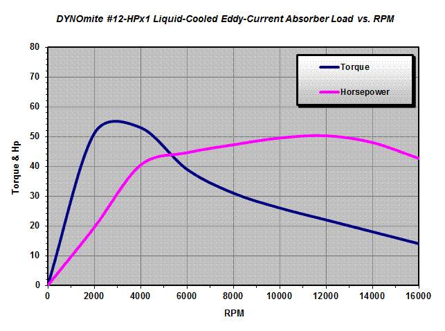
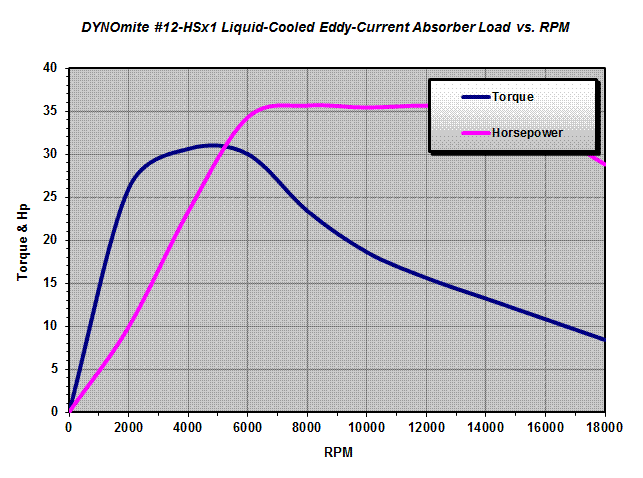
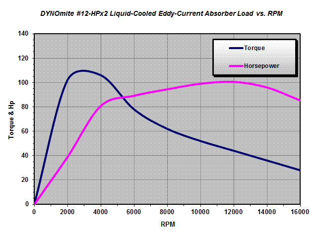
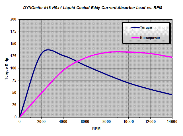
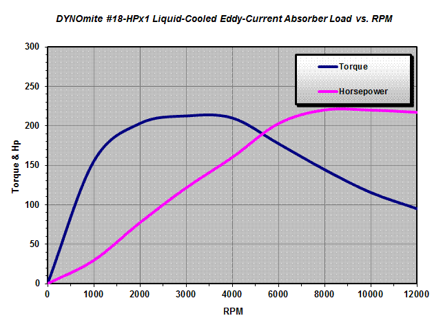
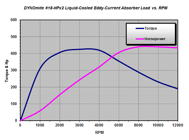
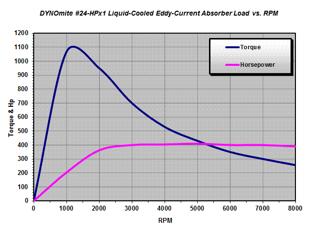
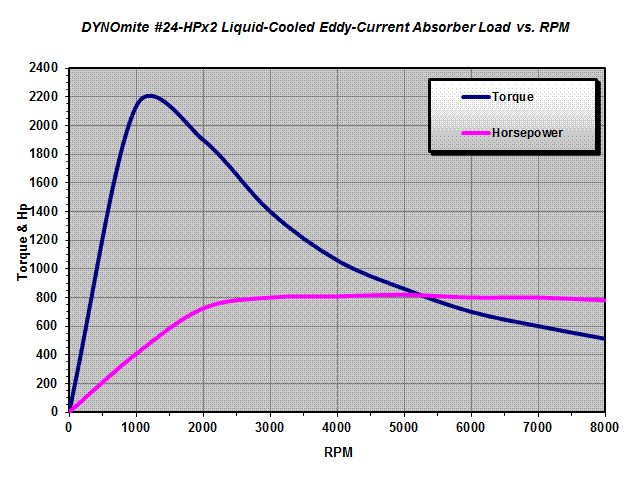
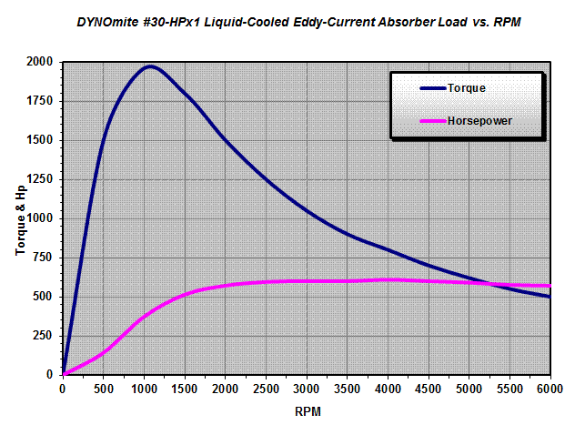
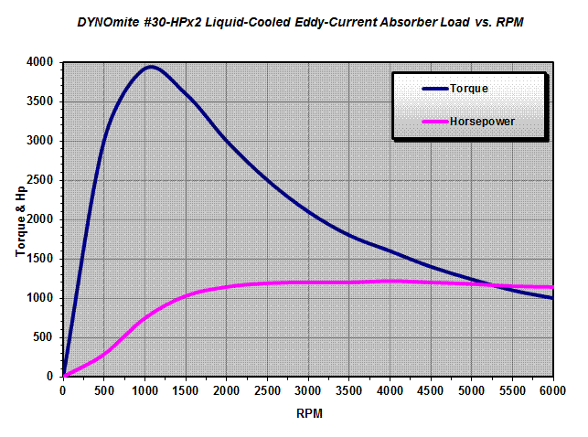
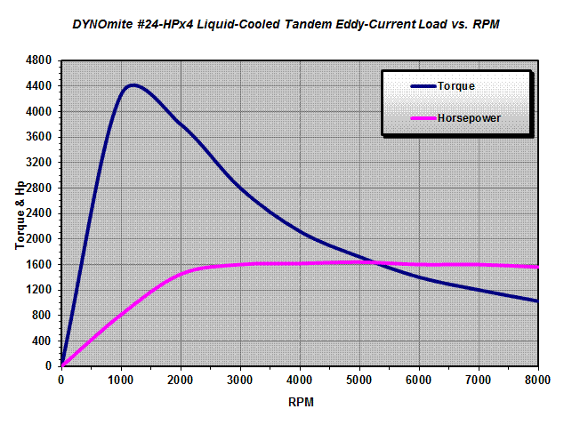
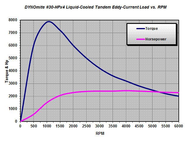
“For better control, the engine being tested should not be at the extreme high or low range of the absorber’s capacity.*”
Important: These curves assume full current flow through the absorber. Lowering the power supply/controller’s amperage output reduces the maximums shown accordingly.
*Approximate; continuous capacities depend on selected absorber and test speed. Liquid-cooled-eddy absorber power capacities are RPM dependent and assume a minimum water supply of 1 gpm @ 60 psi for every 20 continuous Hp. Call Land & Sea, Inc. at (603) 226-3966 for the approximate capacity of any specific test configuration.
WARNING: These are only the magnetic limits for each absorber. They do not take into account any other mechanical limits imposed by the dynamometer’s other driveline hardware.
Typical curves, other capacity liquid-cooled eddy-current units have similar shaped curves (call for charts specific to a model that meets your required Power and RPM range). Note: Model numbers, like #400-1, indicate the maximum power rating is about 400 Hp and that the unit has 1 rotor. For a given power range, more rotors provide a higher speed rating – than a lager-diameter single rotor.
Minimum Hp requirements for most eddy-current absorbers is too low to bother charting. For example, the combined bearing, seal, and windage drag (at 500 RPM) for a #400 absorber is only about 0.625 horsepower (climbing to just 5.0 Hp at 2,000 RPM).
