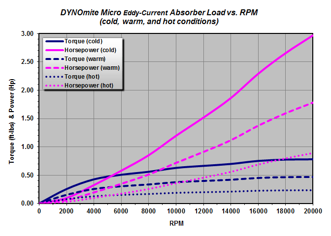
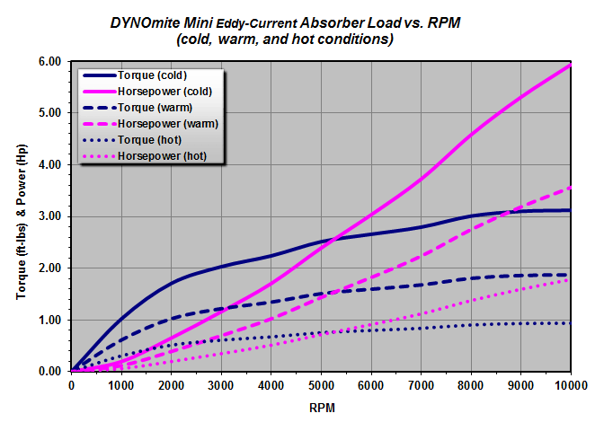
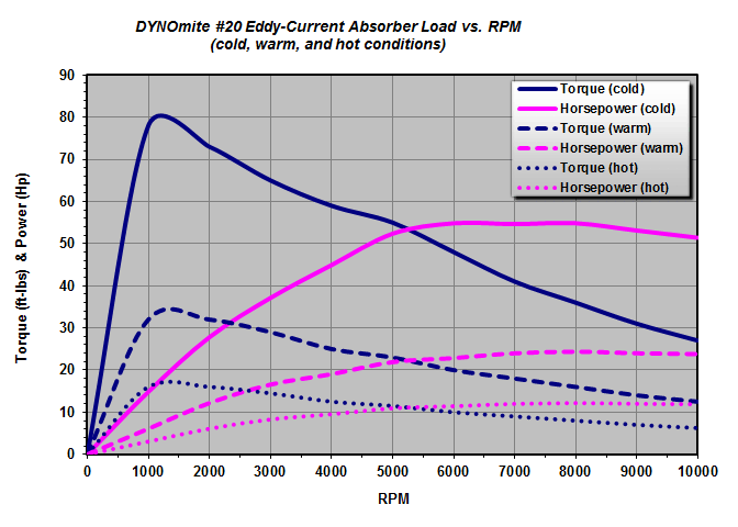
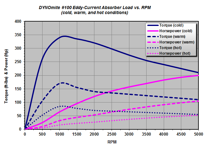
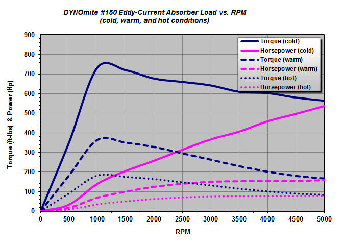
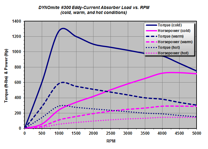
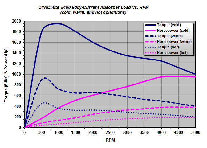
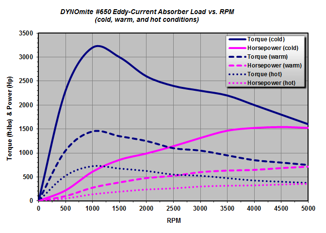
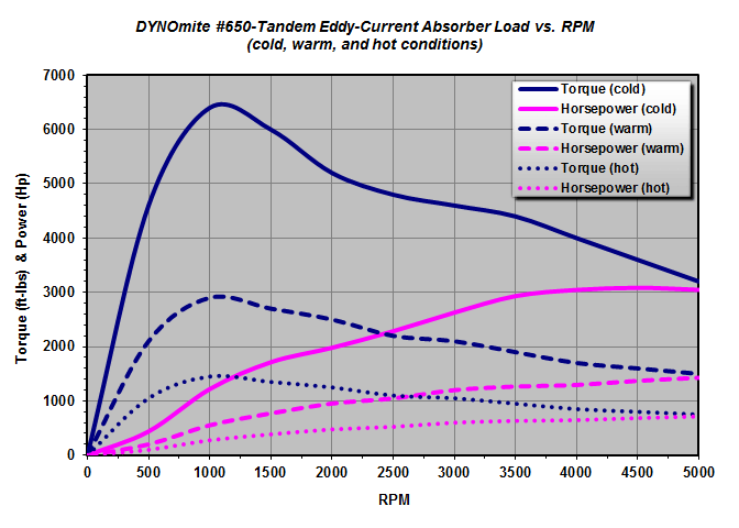
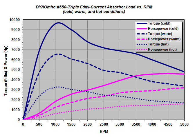
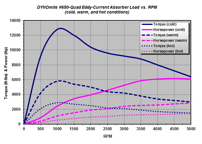
“For better control, the engine being tested should not be at the extreme high or low range of the absorber’s capacity.*”
Important: These curves assume full current flow through the absorber. Lowering the power supply/controller’s amperage output reduces the maximums shown accordingly.
*Actual air-cooled eddy current capacities are RPM and absorber temperature dependent. Initial cold rotor torque (foot-pounds) and power (Hp) curves are for room-temperature rotors. Warm curves are after running about 1+ minutes, at full load, in a room temperature environment. Hot (near continuous) curves assume appropriate forced ventilation to rotors.
Tip: Be sure to consider your applied-power duty cycle and test duration when selecting an air-cooled absorber. Remember, eddy-current absorbers cannot provide any significant loading at near-zero RPM.
WARNING: These are only the magnetic limits for each absorber. They do not take into account any other mechanical limits imposed by the dynamometer’s other driveline hardware.
