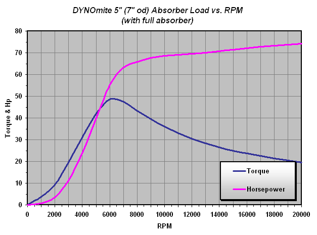
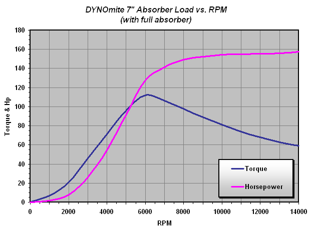
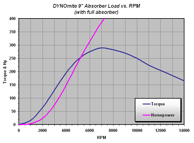
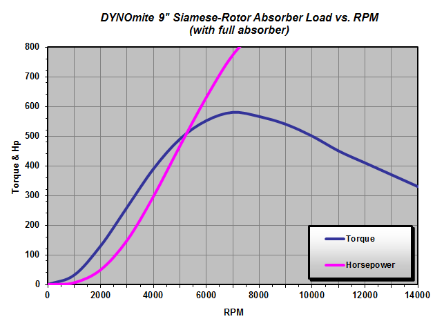
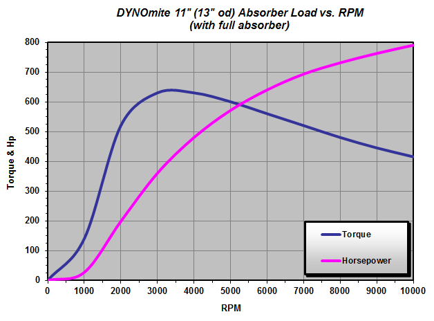
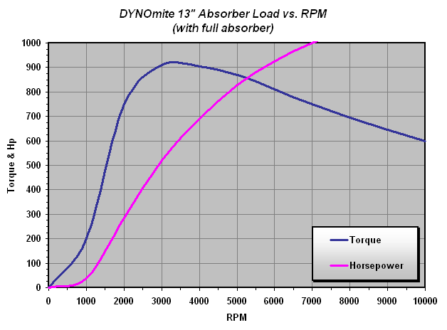
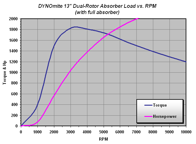
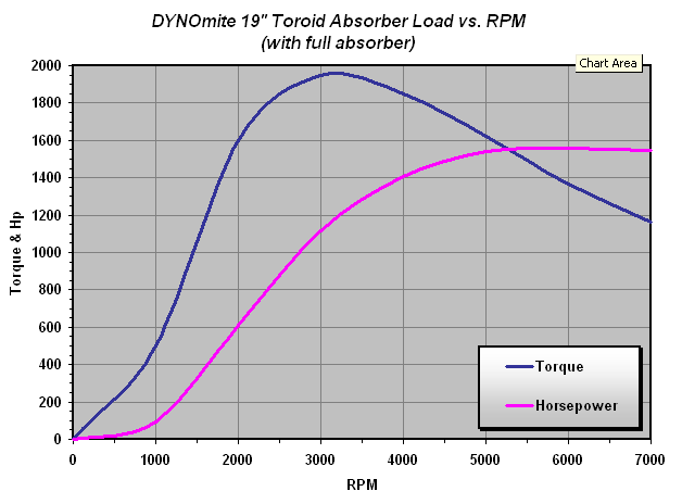
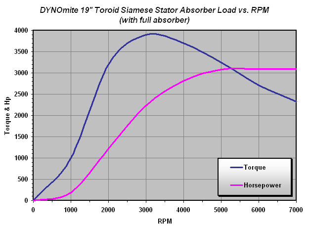
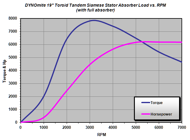
“For better control, the engine being tested should not be at the extreme high or low range of the absorber’s capacity.”
Important: These maximum curves assume a full absorber. If you are running an inadequate water supply system, then you will not be able to reach these maximums.
Minimum Hp requirements for these absorbers is too low to bother charting. For example, our 5″ absorber’s combined bearing, seal, and windage drag (at 5,000 RPM) is only about 0.5 horsepower (climbing to just 2.5 Hp at 10,000 RPM). Note: The DYNOmite’s integral torque arm fully captures this parasitic drag, so these do not represent un-measured power losses!
*Absorber capacities are RPM dependent. Water brakes require a minimum water flow of 1 gpm @ 30 to 60 psi for every 20 continuous Hp. For peak performance, install a supply system capable of maintaining 60 psi @ 1 gpm for every 10 Hp. Install very-high-flow pressure-reducing valve(s) and large water-hammer arrestor(s) to prevent exceeding 60 psi.
