Featured Product
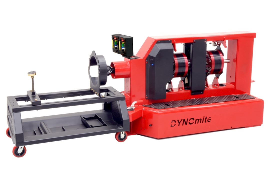
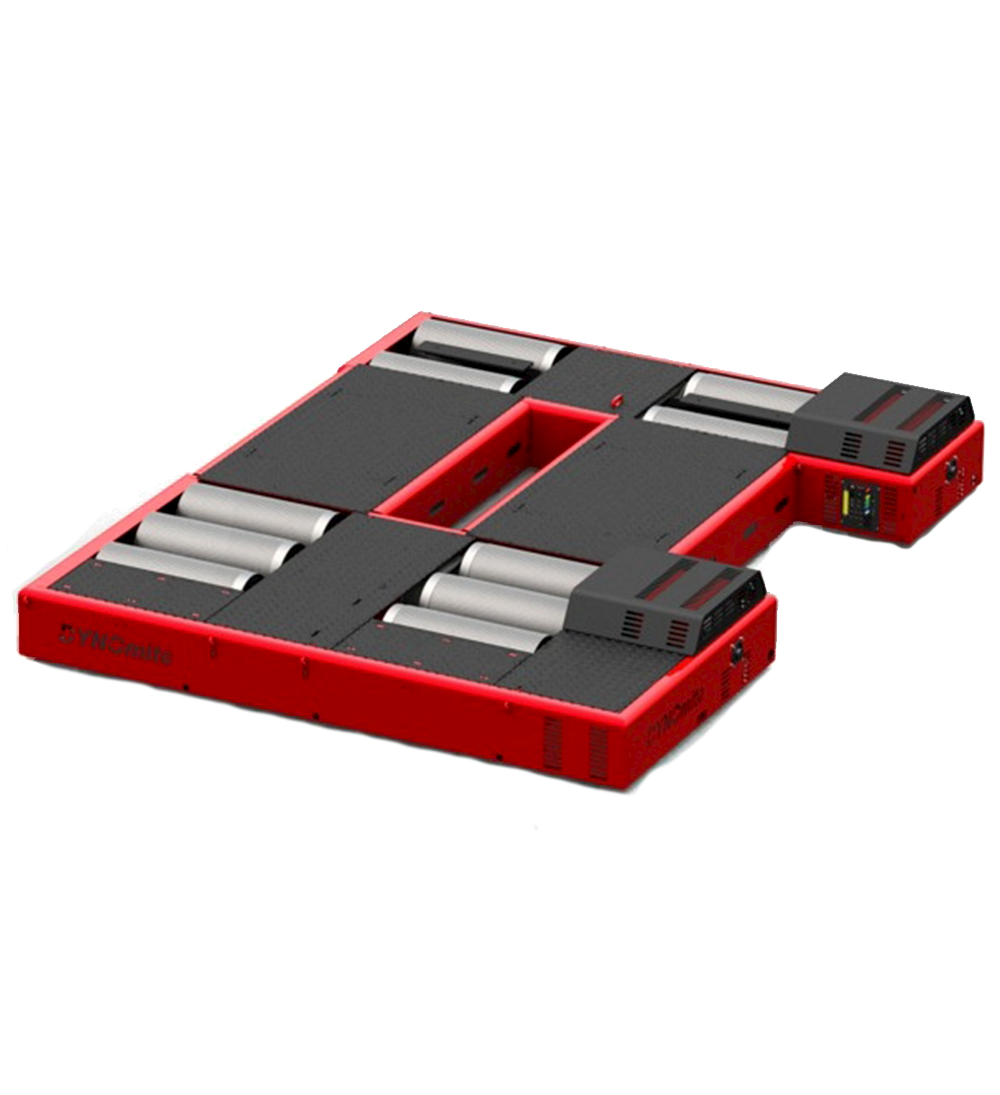
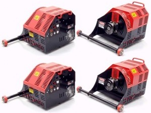
AWD Axle-Hub Dyno
Includes: Four heavy-duty rolling modules with eddy-current controllers and high-speed (medium-inertia) air-cooled absorbers, automatic camber...
Click to learn more.
Explore
Products
Explore the world's largest lineup of dynamometers offered by DYNOmite.
Explore
Industries
Browse our products by industries served. In many cases we offer several products and solutions across multiple departments.
Tech Talk | 09.28.20
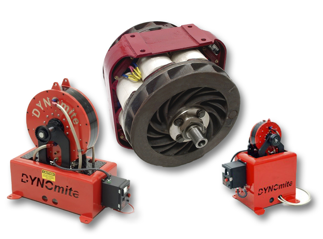
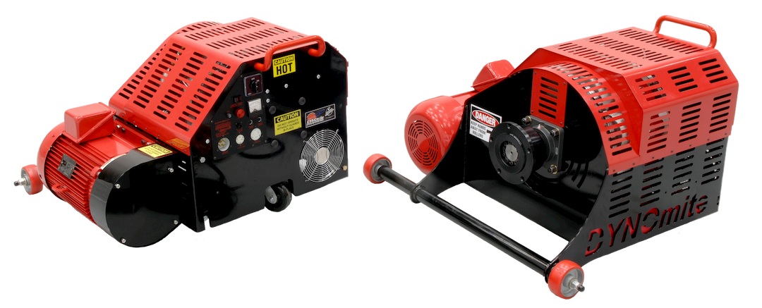
Absorber Comparison
View charts that explain the advantages of various configurations.