“For better control, the engine being tested should not be at the extreme high or low range of the absorber’s capacity.”
Important: These maximum curves assume full current dissipation is available form resistor banks or regenerative provisions.
WARNING: These are only the electrical torque (in foot-pounds) and Hp limits for each absorber. They do not take into account any other mechanical limits imposed by the dynamometer’s hardware.
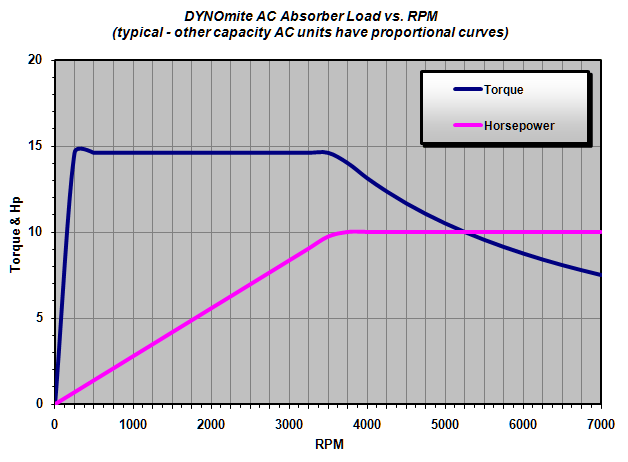
AC absorber loading characteristics are similar to other common AC motor applications. From just above zero RPM, full torque is available. That full torque remains available up to about the motor’s Base RPM specification (i.e. 1,800, 3,600) is reached. Beyond the Base RPM point, near constant power (for loading or motoring) is available – up to the maximum safe working speed of the absorber’s bearings and armature.
Standard Base RPMs include 600, 1200, 1800, and 3600 RPM. With standard bearings the maximum safe working speed is generally in the 7,200 RPM range. Special very high-speed versions, with water-cooled bearings, have speed limits up to the 11,000 RPM range.
Special encoders are available to interface with the drives for applications that require full torque be available down to the Stall RPM point. Without the encoders, about 0.1% of the Base RPM must be exceeded before full torque is available. Without an encoder, a 3,600 Base RPM motor would not be able to deliver its rated torque below 3.6 RPM.
Tip: The typical load (and motoring) chart below is for a 10 Hp AC drive/absorber combination having a Base RPM of 3,600. Much higher and lower capacity absorbers are also available – with similar load profile curves. You may simply scale these Hp and Torque values for other size units. Likewise, other standard Base RPM ranges (1,800, 3,600, etc.) may be ordered. When the Base RPM is changed, the intersection of the “full torque and peak power” RPM point will shift on the graph’s X-axis.
For example: A 100 horsepower AC drive/absorber combination would handle 10 x the loads shown for the 10 Hp unit below.

